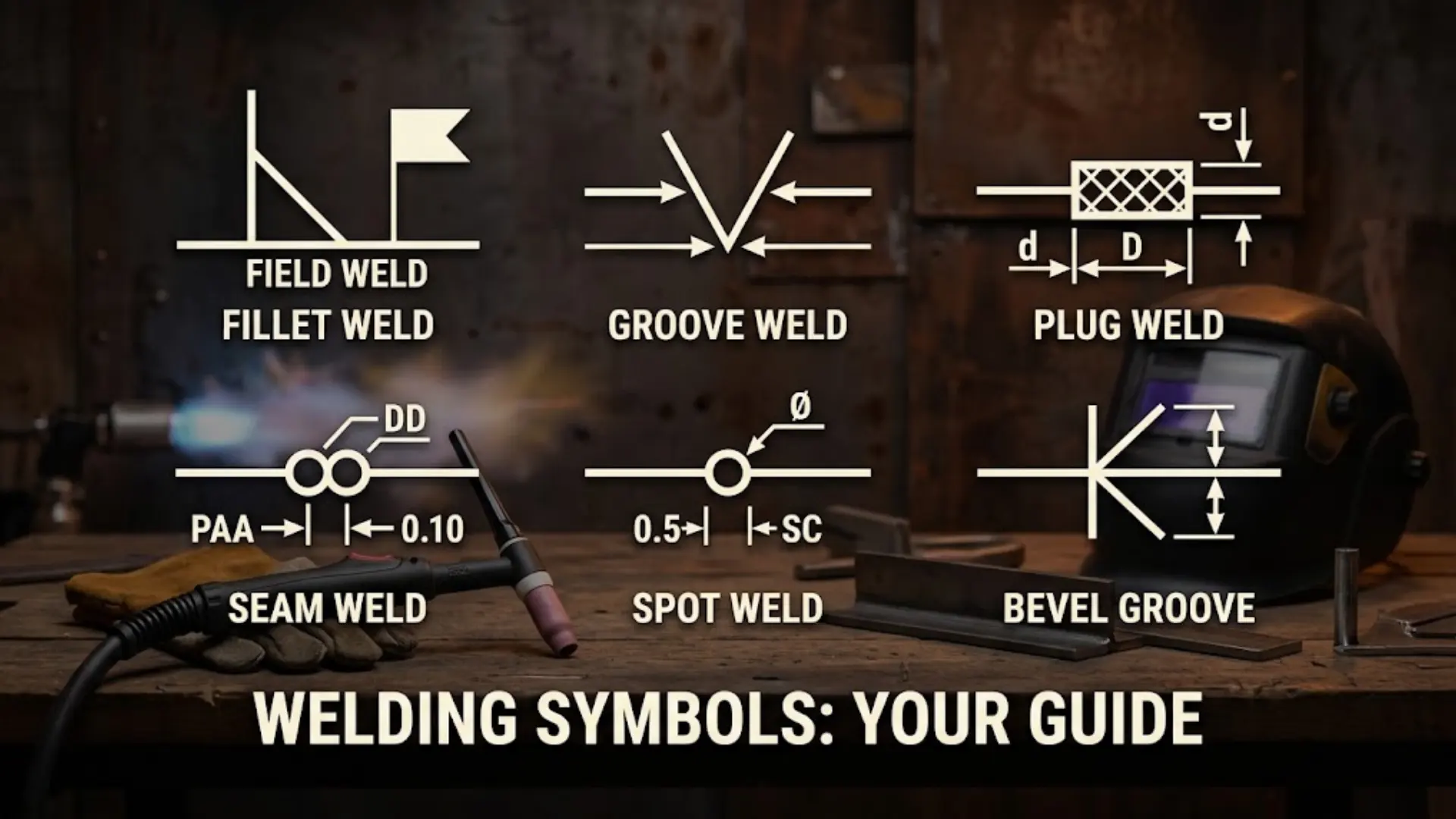
Welding symbols help welders, fabricators, engineers, and inspectors understand exactly what a drawing requires. A small symbol on a blueprint can communicate the type of weld, its location, size, length, spacing, and finishing requirements. Reading these details correctly helps prevent fabrication errors, unnecessary rework, and costly misunderstandings.
However, welding symbols can look confusing when you’re first learning them. A reference line, arrow, triangle, groove shape, or number may carry a specific meaning. The position of a symbol can also change how you interpret the required weld.
This guide explains welding symbols and their meanings, shows how to read common welding symbol charts, and walks through practical examples. You’ll learn the difference between fillet and groove weld symbols, how to interpret dimensions, and how to recognize supplementary symbols on engineering drawings.
Whether you’re a beginner, welding student, fabricator, or experienced professional who needs a quick reference, this guide will help you understand the information behind welding symbols.
What Are Welding Symbols?
Welding symbols are standardized markings used on technical drawings to communicate welding requirements. They provide instructions about the type of weld needed and may specify its location, dimensions, extent, and other details.
Instead of writing a long instruction beside every joint, a designer can use a welding symbol to communicate several requirements in a compact format.
For example, a drawing may show a fillet weld symbol with a specified size. That information tells the fabricator which weld type is required and how large it must be, subject to the drawing’s applicable standard and notes.
Welding symbols are commonly used in:
- Structural steel fabrication
- Manufacturing and machine construction
- Automotive and transportation equipment
- Shipbuilding
- Pressure vessels and piping
- Agricultural and industrial machinery
- Metal furniture and general fabrication
The symbols help everyone involved work from the same instructions. However, a symbol must be interpreted according to the standard referenced by the drawing. In the United States, the American Welding Society’s AWS A2.4 standard is a major reference for welding, brazing, and nondestructive examination symbols. ISO 2553 provides an international system for representing welded joints on technical drawings.
These standards define how symbols and additional information communicate requirements. They do not replace the engineering design, welding procedure, or applicable construction code.
Welding Symbol vs. Weld Symbol: What’s the Difference?
The terms welding symbol and weld symbol are related, but they don’t mean exactly the same thing.
A weld symbol is the basic graphic that identifies a particular type of weld. For example, a triangular graphic represents a fillet weld in the AWS system.
A welding symbol is the complete notation used on a drawing. It may include the weld symbol, reference line, arrow, dimensions, supplementary symbols, and a tail containing additional information.
| Term | Meaning | Example |
| Weld symbol | Identifies the type of weld or joint preparation | Fillet weld symbol |
| Welding symbol | Combines the weld symbol with the necessary instructions | Fillet symbol with size and length |
| Reference line | Provides the main line on which welding information is arranged | Horizontal line |
| Arrow | Connects the symbol to the joint on the drawing | Leader with an arrowhead |
| Supplementary symbol | Adds information about the weld or how it should be finished | Weld-all-around symbol |
| Tail | Provides a place for additional references or instructions | Process or procedure reference |
A simple weld symbol may communicate the weld type, while the complete welding symbol can tell the reader where to apply it and what dimensions or additional requirements to follow.
Main Parts of a Welding Symbol
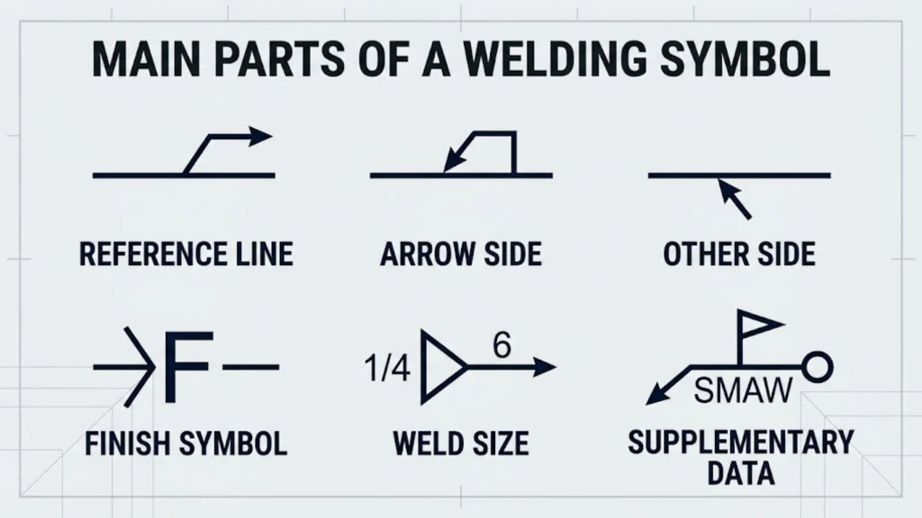
Understanding the basic parts makes a welding symbols chart much easier to use. Most complete welding symbols are built around a few important elements.
Reference Line
The reference line is the main horizontal line in the AWS welding symbol system. The weld symbol and related information are arranged in relation to it.
The reference line helps you determine which side of the joint requires welding. It can also carry dimensions and supplementary information.
When reading a drawing, start with the reference line before interpreting the other details.
Arrow
The arrow connects the welding symbol to the joint that needs attention. Its point identifies the joint on the drawing, rather than simply indicating a general area.
The arrow may point to a visible line or, when appropriate, a hidden line representing the joint. Follow it carefully so you don’t confuse one joint with another nearby.
In the AWS system, the arrow also establishes the arrow side of the joint.
Tail
The tail is the optional forked part at the end of the reference line opposite the arrow. It provides space for information such as a welding process, specification, procedure, or other reference.
A tail may be omitted when the drawing communicates all necessary information elsewhere.
For example, a fabrication drawing might refer to a welding procedure specification (WPS) in the tail or through a drawing note. The welder must consult that reference when it contains requirements needed to complete the work.
Basic Weld Symbol
The basic weld symbol identifies the required weld type or joint preparation. Common examples include:
- Fillet weld
- Square-groove weld
- V-groove weld
- Bevel-groove weld
- U-groove weld
- J-groove weld
- Plug weld
- Slot weld
- Spot weld
- Seam weld
- Stud weld
Each symbol has a specific shape defined by the governing standard. Don’t rely on memory alone when an unfamiliar symbol appears on a production drawing.
Dimensions and Additional Instructions
Numbers and supplementary symbols add details that the basic weld symbol cannot communicate by itself.
Depending on the weld type, a drawing may specify:
- Weld size
- Weld length
- Intermittent weld pitch
- Groove angle
- Root opening
- Groove depth
- Number of welds
- Weld contour
- Finishing method
The meaning and placement of these details depend on the weld type and the applicable standard.
How to Read Welding Symbols Step by Step
Reading a welding symbol becomes easier when you follow a consistent process.
Identify the Joint
Begin with the arrow. Find the joint it points to on the blueprint or fabrication drawing.
Check the surrounding geometry and dimensions to confirm that you’ve located the correct joint. This matters when several plates, brackets, or members meet in the same area.
Check the Reference Line
Next, locate the weld symbol relative to the reference line. Under the AWS convention, a symbol below the line indicates welding on the arrow side. A symbol above the line indicates welding on the other side.
This convention is especially important when a joint is accessible from either side.
Identify the Weld Type
Look at the basic symbol to determine whether the drawing calls for a fillet, groove, plug, slot, spot, seam, or another weld type.
The shape tells you what kind of weld is required. The surrounding dimensions and notes explain the details.
Read the Dimensions
Check for dimensions associated with the symbol. These may specify weld size, length, pitch, groove angle, root opening, or another feature.
Don’t assume every number refers to the same measurement. A dimension placed beside a fillet weld symbol has a different purpose from a number specifying the angle of a groove preparation.
Look for Supplementary Symbols
Check for symbols indicating a field weld, weld-all-around requirement, contour, or finish method.
These details can affect where the weld is made and the required appearance of the finished weld.
Read the Tail and Drawing Notes
Finally, check the tail, title block, general notes, joint details, and referenced specifications.
The welding symbol may not contain every requirement. The complete drawing package and applicable welding procedure may provide additional instructions about materials, processes, inspection, and acceptance criteria.
Welding Symbols Chart: Common Symbols and Their Meanings
The following chart summarizes common weld categories and their applications. The actual graphics should be checked against the applicable AWS or ISO symbol chart before interpreting a production drawing.
| Weld type | Symbol identification | Common application |
| Fillet weld | Triangle | T-joints, lap joints, and corner joints |
| Square-groove weld | Square-groove graphic | Suitable butt joints with square edges |
| V-groove weld | V-shaped graphic | Butt joints requiring V-shaped preparation |
| Bevel-groove weld | Bevel-shaped graphic | Joints where one member has a beveled edge |
| U-groove weld | U-shaped graphic | Joints requiring U-shaped preparation |
| J-groove weld | J-shaped graphic | Joints requiring J-shaped preparation |
| Flare-V-groove weld | Flare-V graphic | Joints involving rounded surfaces |
| Flare-bevel-groove weld | Flare-bevel graphic | Joints involving a rounded surface and a beveled member |
| Plug weld | Circular-hole weld notation | Joining overlapping members through holes |
| Slot weld | Elongated-slot weld notation | Joining overlapping members through slots |
| Spot weld | Spot-weld graphic | Localized welds, often in sheet metal |
| Seam weld | Seam-weld graphic | Continuous or specified seam joining |
| Stud weld | Stud-weld graphic | Attaching studs to a base component |
| Surfacing weld | Surfacing-weld graphic | Building up or restoring a surface |
| Edge weld | Edge-weld graphic | Joining edges in specified edge-joint configurations |
Important: A symbol’s shape, dimensions, and placement must follow the standard used on the drawing. A general chart is a learning aid, not a substitute for the official standard or project requirements.
Fillet Welding Symbols and Their Meanings
Fillet welds are common in fabrication because they join members that meet at an angle. They’re frequently used in T-joints, lap joints, and corner joints.
Fillet Weld Symbol
In the AWS system, the fillet weld symbol is triangular. It appears on the reference line, and its position indicates the side of the joint where the weld is required.
A single fillet weld may be specified on one side of the joint. When welding is required on both sides, the symbol may appear on both sides of the reference line.
For example, a bracket attached to a plate may require a fillet weld along one edge. The drawing identifies the joint and uses the symbol and dimensions to define the required weld.
Fillet Weld Size
Fillet weld size is commonly expressed through the leg dimensions. The leg length is measured from the joint root to the toe of the weld along the adjoining surfaces.
For a typical equal-leg fillet weld, the nominal theoretical throat is related to the leg size. For a 90-degree equal-leg fillet, the theoretical throat is approximately 0.707 times the leg length.
For example, an equal-leg fillet with a leg length of 6 mm has a theoretical throat of about 4.2 mm. This is a geometric relationship, not a substitute for the specified effective throat or design requirements.
The drawing’s dimensions and applicable design code determine what size is required.
Intermittent Fillet Weld Symbols
An intermittent fillet weld consists of separate weld segments rather than one continuous weld along the entire joint.
Two important dimensions are:
- Weld length: The length of each individual weld segment.
- Pitch: The distance between corresponding points on adjacent weld segments, commonly measured center to center.
Suppose a drawing specifies weld segments that are 50 mm long at a pitch of 150 mm. The segments are spaced at that specified interval along the joint. The exact start and end positions must be interpreted from the drawing and its notes.
Intermittent welds may be arranged in two common patterns:
- Chain intermittent welds: Weld segments on opposite sides of the joint line up with each other.
- Staggered intermittent welds: Segments on opposite sides alternate rather than lining up directly.
The correct arrangement must be identified from the symbol and the governing standard.
Continuous Fillet Welds
A continuous fillet weld extends along the specified joint length without intentional gaps between weld segments.
The drawing may specify the weld size and use the joint geometry or additional dimensions to establish its extent. If a weld-all-around symbol is also present, it communicates a perimeter requirement as defined by the standard.
A continuous weld should not be assumed to extend farther than the drawing indicates.
Groove Welding Symbols and Their Meanings
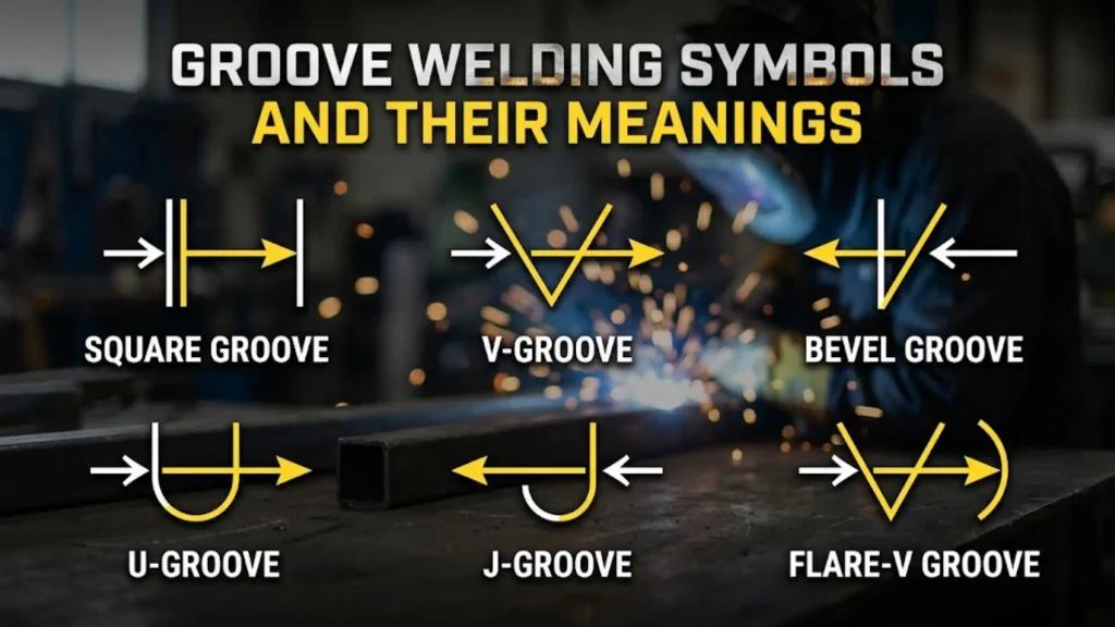
Groove welds involve preparing the joint edges or surfaces to create a groove that receives weld metal. They’re commonly used in butt joints and other connections where the specified design calls for groove preparation.
The required groove shape depends on factors such as member thickness, joint access, material, welding process, and design requirements.
Square-Groove Weld Symbol
A square-groove weld uses square edges rather than a V-shaped or curved groove preparation.
It’s suitable for certain joint configurations when the design and welding procedure permit it. The drawing may specify a root opening or other dimensions that control the joint fit-up.
Don’t assume that every square-groove joint requires no gap. Follow the specified dimensions.
V-Groove Weld Symbol
A V-groove joint has beveled edges that form a V-shaped opening. The drawing may show a single-V or double-V groove.
Common details include:
- Groove angle
- Root opening
- Groove depth
- Required weld size, where specified
- Joint preparation details
A double-V preparation may be used when the design calls for welding from both sides of a joint. However, the choice depends on the design, material thickness, access, and approved procedure.
Bevel-Groove Weld Symbol
A bevel-groove joint has a beveled edge on one member while the adjoining member remains square, creating a groove for welding.
This preparation is useful when the joint design calls for beveling only one member. The drawing must identify the joint and provide the required dimensions.
Under AWS conventions, the arrow can have particular significance in identifying the member requiring bevel preparation. Check the official symbol rules rather than interpreting the arrow as a simple pointer to the entire joint.
U-Groove and J-Groove Weld Symbols
U-groove and J-groove joints use curved groove preparations.
A U-groove has a rounded U-shaped preparation, while a J-groove has a J-shaped preparation. These shapes may be specified when the joint design requires a particular groove geometry.
The preparation can affect the amount of weld metal required, the machining or cutting operation, and access for welding. The actual requirements come from the drawing and approved procedure.
Flare-V and Flare-Bevel Groove Weld Symbols
Flare-groove welds are associated with joints involving rounded surfaces.
A flare-V groove is formed by two rounded surfaces, while a flare-bevel groove involves a rounded surface adjoining a beveled member.
These symbols help communicate joint configurations that don’t resemble a conventional V-groove between two flat, beveled edges.
Groove Dimensions and Root Information
Groove weld drawings may specify several measurements. These must be interpreted separately.
| Dimension | Meaning |
| Groove angle | The angle formed by the prepared groove surfaces |
| Root opening | The separation between members at the root of the joint |
| Groove depth | The depth of the prepared groove |
| Weld size | The specified weld dimension as defined by the applicable symbol and standard |
| Backing information | Requirements relating to material or other provisions supporting the weld root |
| Melt-through information | A requirement concerning root penetration or reinforcement, as defined by the applicable standard |
Backing, back welds, backing welds, and melt-through are not interchangeable terms. Each has its own meaning, and the drawing’s notation must be read accordingly.
Other Common Welding Symbols
Plug and Slot Weld Symbols
Plug and slot welds join overlapping members using openings in one component.
A plug weld is made in a hole, while a slot weld is made in an elongated opening. The drawing may specify dimensions, spacing, orientation, or the number of welds.
These welds are used in selected designs where the joint geometry and load requirements support their use. A plug or slot weld symbol doesn’t mean that any convenient hole or slot can be used; the dimensions must follow the drawing.
Spot and Seam Weld Symbols
Spot and seam welds are common in resistance welding, particularly in sheet metal work.
A spot weld joins components at a localized point or area. A seam weld forms a welded seam along a specified path.
The symbol may be accompanied by dimensions or other information required by the governing standard. Process-specific details may appear elsewhere in the drawing or in the welding procedure.
Stud Weld Symbol
Stud welding attaches a stud or similar component to a base material.
The welding symbol identifies the required connection. Additional instructions may specify the stud type, size, location, or related requirements through the drawing and referenced documentation.
Surfacing Weld Symbol
A surfacing weld deposits weld metal onto an existing surface. It may be used to restore dimensions, build up material, or provide a surface with specified properties.
Surfacing differs from a conventional joint weld because the purpose is to add material to a surface rather than simply join two members.
Edge Weld Symbol
An edge weld joins members along their edges in a specified edge-joint configuration.
It isn’t the same as a fillet weld. The correct symbol depends on the joint design, and the required dimensions and extent must be interpreted from the drawing.
Supplementary Welding Symbols and What They Mean
Supplementary symbols add information to the basic weld symbol. They can indicate the weld’s extent, location, contour, or finishing requirements.
Weld-All-Around Symbol
In the AWS system, a small circle at the junction of the arrow and reference line indicates a weld-all-around requirement.
It tells the reader that the weld is to extend around the perimeter of the joint as specified. It doesn’t mean that every joint on the assembly must be welded, nor does it independently define the weld size.
The weld type and dimensions still come from the rest of the symbol.
Field Weld Symbol
A field-weld symbol is a flag used to indicate that the weld is to be made in the field rather than in the shop.
This distinction can affect assembly planning, access, and fabrication logistics. The drawing or project specifications may also define requirements for field welding.
Contour Symbols
Contour symbols communicate the required shape of the finished weld surface.
Common contour requirements include:
- Flat: The surface is intended to be flat or flush as specified.
- Convex: The surface has an outward curve.
- Concave: The surface curves inward.
The contour requirement should be read together with any finishing instruction. The symbol indicates the required profile, while a finish designation may explain how that profile is to be achieved.
Finish Symbols
A finish designation may accompany a contour symbol to identify a finishing method. In AWS conventions, common letters include:
- G: Grinding
- M: Machining
- C: Chipping
Always check the applicable edition and standard before interpreting an unfamiliar designation. A finish-method letter communicates a process, not a guarantee that the finished weld meets every inspection or quality requirement.
Backing and Melt-Through
Backing and melt-through information can be important for groove welds.
Backing may involve material placed at the root or another specified provision used to support the weld. A backing weld is a weld made on the reverse side in accordance with the applicable requirements. Melt-through notation addresses a specified root-penetration or reinforcement condition.
Because these details affect joint preparation and the finished weld, don’t treat them as interchangeable. Use the official symbol chart and the project specification when interpreting them.
Welding Symbol Dimensions: How to Read the Numbers
The numbers around a welding symbol explain important measurements. Their placement depends on the weld type and the governing standard.
Weld Size and Depth
For fillet welds, the size commonly refers to the leg dimension. Groove weld dimensions may refer to the groove preparation, depth, or required weld size as specified.
Read the number in context. A dimension beside a fillet weld symbol should not automatically be interpreted as a throat measurement.
Weld Length and Pitch
Weld length indicates the length of an individual weld or the specified weld extent. Pitch is used for intermittent welds and refers to the spacing between repeated weld segments, commonly measured from center to center.
For example, an intermittent weld specification may identify segments of a stated length repeated at a stated pitch. The drawing’s notation and standard determine how these dimensions are displayed.
Groove Angle and Root Opening
The groove angle describes the angle between prepared groove surfaces. The root opening describes the gap between members at the joint root.
Both can affect joint preparation and the welding operation. If the drawing specifies these dimensions, they must be maintained within the applicable requirements.
Quantity and Spacing
Some symbols or related notes specify the number of welds and their spacing. These details are especially relevant for repeated spot welds, plug welds, and other regularly spaced welds.
Don’t assume that the number of visible symbols on a drawing represents the total weld quantity. Check the notation, drawing views, and related notes.
Inches, Millimeters, and Drawing Units
Drawings may use inches, millimeters, or another specified unit system. Check the title block and drawing notes before using a dimension.
A value such as 6 could mean 6 mm or 6 inches depending on the drawing. Guessing can lead to a serious fabrication error.
Welding Symbols Above and Below the Reference Line
Symbol placement is one of the most important parts of reading welding drawings.
Under the AWS convention:
- A weld symbol below the reference line indicates the arrow side of the joint.
- A weld symbol above the reference line indicates the other side.
- Symbols shown on both sides of the reference line indicate welds on both sides, where specified.
The arrow side is the side of the joint to which the arrow points. The other side is the opposite side.
This rule is not universal across every international drawing system. ISO 2553 recognizes different approaches to identifying the arrow side and other side, including systems based on a single or dual reference line.
Always identify the governing standard before interpreting symbol placement. A symbol that looks similar may be used under a different convention on an international drawing.
AWS Welding Symbols vs. ISO Welding Symbols
AWS A2.4 and ISO 2553 both provide systems for representing welding requirements on technical drawings, but their conventions are not identical.
AWS Welding Symbols
AWS A2.4 is widely used in the United States and covers symbols for welding, brazing, and nondestructive examination. It explains how symbols communicate the location, extent, and other requirements of the work.
In the AWS system, the reference line and arrow are core elements. The placement of weld information above or below the reference line helps identify the side of the joint.
ISO Welding Symbols
ISO 2553 defines rules for representing welded joints on technical drawings. It covers information about joint geometry, manufacture, quality, and testing.
The standard recognizes two approaches for designating the arrow side and other side. This is one reason international drawings require careful interpretation.
Key Differences Between AWS and ISO
| Feature | AWS system | ISO system |
| Main reference | AWS A2.4 | ISO 2553 |
| Primary purpose | Communicating welding, brazing, and examination requirements | Representing welded joints and related requirements |
| Side identification | Uses AWS reference-line placement conventions | Uses the selected ISO reference-line system |
| Additional information | Dimensions, supplementary symbols, tail information, and drawing references | Dimensions, supplementary symbols, tail information, and drawing references |
| Best practice | Follow the drawing’s AWS requirements | Follow the drawing’s specified ISO system |
For authoritative information, consult the AWS A2.4 standard and the ISO 2553 standard page.
Welding Process Abbreviations in Drawings
Welding process abbreviations may appear in a symbol’s tail, a drawing note, or a related welding procedure. These abbreviations identify the process, not the weld type.
| Abbreviation | Full name |
| SMAW | Shielded Metal Arc Welding |
| GMAW | Gas Metal Arc Welding |
| GTAW | Gas Tungsten Arc Welding |
| FCAW | Flux-Cored Arc Welding |
| SAW | Submerged Arc Welding |
For example, GMAW identifies a welding process. A fillet weld symbol identifies a weld type. One doesn’t replace the other.
A drawing may reference a welding procedure specification (WPS) for details such as process parameters, filler metal, preheat, and other applicable variables. The symbol alone should not be assumed to contain all these requirements.
Welding Symbols in Engineering Drawings and Blueprints
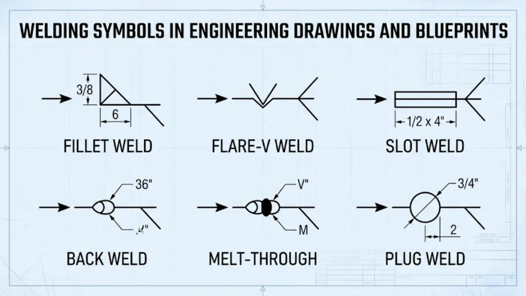
Welding symbols are used across many types of technical drawings, but their purpose remains the same: to communicate the required weld and its details.
Structural Steel Drawings
Structural steel drawings may include weld symbols for beams, columns, plates, brackets, stiffeners, and other connections.
The symbols help identify weld types and dimensions. However, the engineer’s design details, applicable structural code, and project specifications determine the required connection and its acceptance criteria.
Fabrication and Mechanical Drawings
Manufacturing and fabrication drawings use welding symbols to communicate how parts should be joined.
A symbol may identify a fillet weld along a bracket or a groove weld in a butt joint. The drawing’s dimensions and details establish the joint geometry and weld extent.
Piping Drawings
Piping fabrication drawings may identify weld locations and requirements. Other documents, such as weld maps, joint numbers, inspection records, and piping specifications, can provide additional information.
Don’t confuse a welding symbol with a weld identification number or inspection mark. Each has a different purpose.
Welding Symbol Examples With Explanations
The following examples use simplified descriptions rather than reproducing official symbol graphics. The notation and dimensions are illustrative only; always use the applicable standard for an actual job.
Example: Single-Sided Fillet Weld
Imagine a bracket attached to a plate with a fillet weld on one side.
The symbol identifies the fillet weld, while its placement relative to the reference line indicates the side of the joint under the AWS convention. A dimension next to the symbol specifies the required size.
To interpret it correctly, identify the joint, check the side, read the size, and confirm the required weld length.
Example: Double-Sided Fillet Weld
A T-joint may require fillet welds on both sides.
The symbol communicates the weld requirement on each side of the joint. Check whether the drawing specifies the same size on both sides or different dimensions for each.
Don’t assume the two welds are identical unless the notation says so.
Example: Intermittent Fillet Weld
Suppose a drawing specifies 50 mm-long weld segments at a 150 mm pitch.
This means each segment is 50 mm long and the specified pitch is 150 mm, commonly measured center to center. The symbol or drawing details also establish whether the segments are arranged in a chain or staggered pattern.
Example: Single-V Groove Weld
A butt joint may use a V-groove preparation. The drawing can specify the groove angle, root opening, and other relevant dimensions.
The symbol identifies the groove type, while the dimensions establish the required preparation. The welding procedure and drawing notes may specify additional requirements.
Example: Weld-All-Around
A weld-all-around circle indicates that the specified weld extends around the joint’s perimeter.
Read the circle with the main weld symbol and dimensions. The circle doesn’t independently identify the weld type or size.
Example: Field Weld
A flag at the reference-line junction indicates a field weld under AWS conventions.
This tells the team that the specified weld is to be made in the field rather than in the shop. Other project requirements may govern access, sequence, and inspection.
Example: Contour and Finish
A weld symbol may include a contour requirement and a finish designation.
The contour describes the required finished profile, while the finish letter identifies a method such as grinding or machining under the applicable convention. Both details should be checked before completing the weld.
Example: Process Reference in the Tail
A tail may contain a process abbreviation or a reference to a procedure or specification.
Read that information together with the main weld symbol. If the reference points to a WPS or another controlled document, consult that document before welding.
Common Welding Symbol Reading Mistakes
Even experienced fabricators can misinterpret a symbol when they overlook its placement or the drawing’s standard.
Avoid these common errors:
- Confusing a weld symbol with a welding symbol. The weld symbol identifies the weld type; the complete welding symbol may include several additional instructions.
- Misreading the arrow side. Under AWS conventions, a symbol below the reference line refers to the arrow side.
- Mixing AWS and ISO conventions. Identify the governing standard before interpreting the reference line.
- Confusing leg size with throat thickness. These are different measurements.
- Misreading pitch. Intermittent weld pitch is commonly measured center to center, not simply as the open gap between weld segments.
- Ignoring supplementary symbols. A field-weld or weld-all-around symbol can change how the work is performed.
- Treating backing and melt-through as identical. These notations have distinct meanings.
- Guessing the drawing units. Confirm whether dimensions are in inches or millimeters.
- Assuming the symbol specifies everything. Welding procedures, codes, specifications, and notes may contain essential requirements.
When a symbol is unclear, stop and check the drawing standard, official chart, and applicable project documentation. Ask the responsible engineer or welding coordinator to resolve any ambiguity before fabrication.
What Welding Symbols Don’t Tell You by Themselves
A welding symbol communicates specified welding requirements, but it doesn’t necessarily provide every detail needed to complete or inspect the weld.
Additional documents may define:
- Base material and filler metal requirements
- Welding process and procedure parameters
- Preheat and interpass temperature requirements
- Welder qualification requirements
- Inspection methods and acceptance criteria
- Applicable construction codes and project specifications
A welding procedure specification (WPS) describes the applicable welding variables and instructions for a qualified or otherwise approved procedure, as required by the governing code or project. Supporting procedure qualification documentation may also be required.
Similarly, a weld symbol doesn’t automatically establish whether a joint needs visual inspection, radiographic testing, ultrasonic testing, or another examination method. Follow the drawing and applicable specifications for those requirements.
How to Learn and Memorize Welding Symbols
The easiest way to learn welding symbols is to study the basic elements first and then practice reading complete examples.
Start with these steps:
- Learn the reference line, arrow, and tail.
- Memorize the basic fillet and groove weld symbols.
- Practice identifying the arrow side and other side.
- Learn how to read weld size, length, and pitch.
- Study supplementary symbols separately.
- Use an official chart for the standard referenced by your drawing.
- Practice with annotated engineering drawings and fabrication examples.
- Check your interpretation against the drawing notes and relevant specifications.
A useful approach is to cover the symbol’s explanation on a chart and try to identify the weld type yourself. Then check the answer and explain what the reference line, dimensions, and supplementary symbols communicate.
Don’t memorize shapes in isolation. Learning how each element works with the others will help you interpret unfamiliar symbols more reliably.
Frequently Asked Questions About Welding Symbols
What are the most common welding symbols?
Common symbols include fillet, square-groove, V-groove, bevel-groove, plug, slot, spot, seam, stud, surfacing, and edge weld symbols. Fillet and groove weld symbols are especially useful to learn first because they appear in many fabrication and engineering drawings.
What does a triangle mean on a welding drawing?
In the AWS system, the triangular weld symbol identifies a fillet weld. Its placement relative to the reference line indicates the required side of the joint. Dimensions and additional symbols communicate the size and other requirements.
What does a circle at the arrow mean?
A circle at the junction of the arrow and reference line indicates a weld-all-around requirement under AWS conventions. It communicates the weld’s extent around the joint’s perimeter, as specified by the drawing.
What does a flag on a welding symbol mean?
A flag identifies a field weld under AWS conventions. It indicates that the specified weld is to be made in the field rather than in the shop.
What does a welding symbol above or below the line mean?
Under AWS conventions, a symbol below the reference line indicates a weld on the arrow side, while a symbol above the line indicates the other side. ISO 2553 has its own defined approaches, so always confirm the standard used by the drawing.
How do you read the size of a fillet weld?
Locate the size dimension beside the fillet weld symbol and interpret it according to the applicable standard. For a conventional equal-leg fillet, the leg length and theoretical throat thickness are different measurements.
What do length and pitch mean in an intermittent weld symbol?
Length identifies the length of each weld segment. Pitch commonly identifies the center-to-center spacing between adjacent segments. The drawing’s notation determines how those dimensions apply.
What is the difference between a weld symbol and a welding symbol?
A weld symbol identifies the weld type or joint preparation. A welding symbol is the complete notation that can include the reference line, arrow, weld symbol, dimensions, supplementary symbols, and tail information.
Where can I find an official welding symbols chart?
The American Welding Society publishes welding symbol charts and AWS A2.4, its standard for symbols used in welding, brazing, and nondestructive examination. You can explore the AWS A2 committee and published standards. For international drawings, consult the ISO 2553 standard page.
Conclusion
Welding symbols communicate essential information about the type, location, dimensions, and other requirements of a weld. Learning to read the reference line, arrow, basic weld symbol, dimensions, and supplementary symbols gives you a reliable foundation for understanding engineering drawings.
Start with fillet and groove weld symbols, then practice interpreting intermittent welds, weld-all-around requirements, field-weld flags, and finishing instructions. Most importantly, identify the standard used on the drawing before interpreting its conventions.
A welding symbols chart is a useful reference, but accurate interpretation also requires attention to drawing notes, units, welding procedures, and applicable specifications. When you understand how these details work together, you’ll be better prepared to read blueprints and communicate welding requirements clearly.

Hi, I’m Asher Monroe, a writer who believes that meaningful words have the power to inspire change and bring people closer to their dreams. I have always been fascinated by the beauty of quotes and the way a simple message can provide motivation, hope, and comfort.
I enjoy creating content around inspirational quotes, life lessons, success stories, and positive thoughts that help readers find encouragement in their everyday lives. My goal is to share words that connect with people and remind them of their inner strength.
Through my writing, I explore the ideas of personal growth, confidence, and the importance of staying inspired through every chapter of life.
I am the author of Words That Move the Soul and The Path of Endless Inspiration, two books focused on the power of wisdom, positivity, and meaningful thoughts.
 Sienna Brooks
 Rowan Sinclair Rowan Sinclair