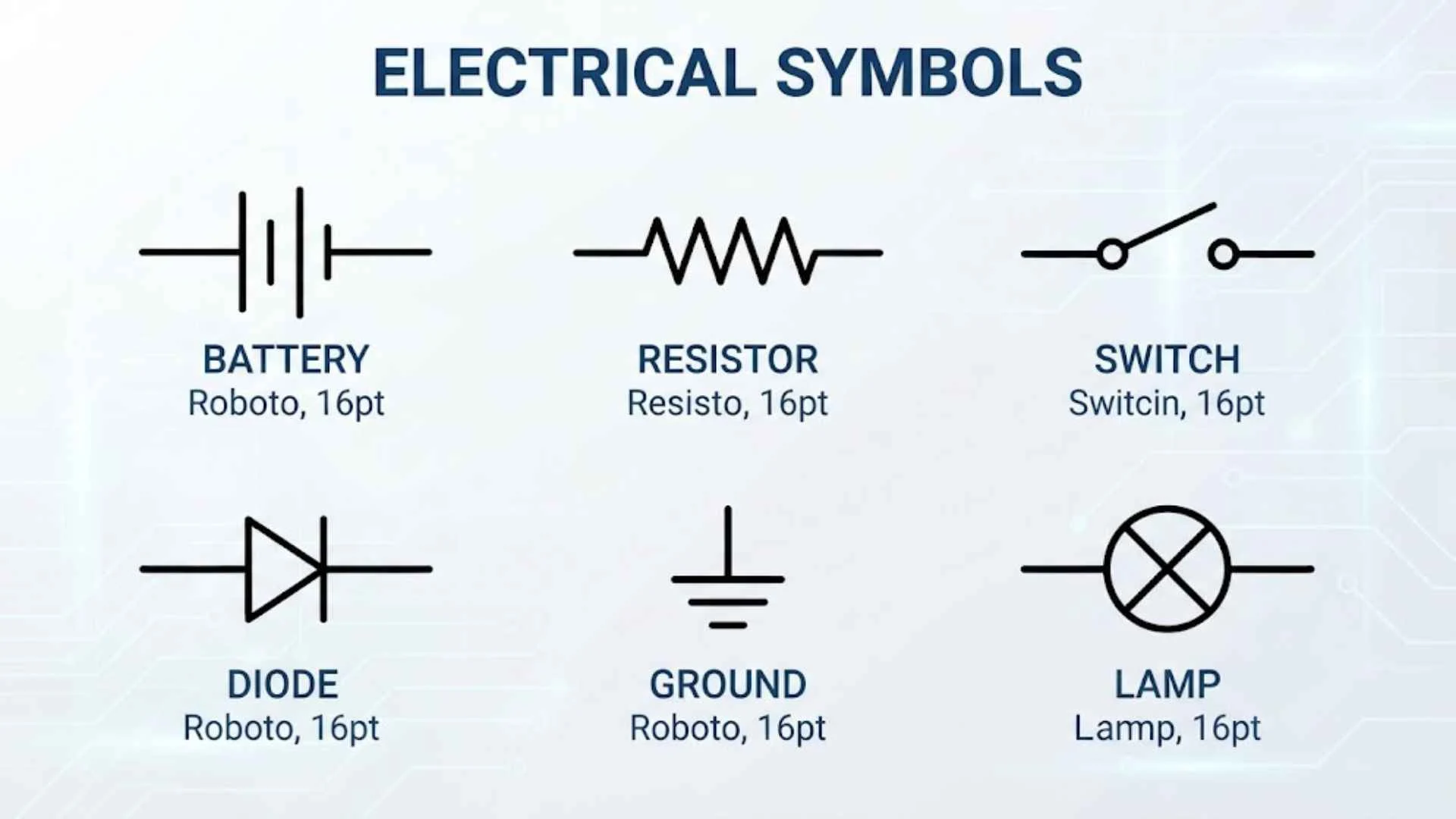
Electrical symbols are the visual language used to represent components, devices, connections, and functions in electrical drawings. Instead of writing long descriptions for every component, engineers, electricians, designers, and technicians use standardized or commonly recognized symbols to make drawings easier to read.
This guide covers electrical symbols with names and meanings, common symbols, drawing and blueprint symbols, HVAC and automotive symbols, residential applications, and computer-aided design tools such as AutoCAD and CAD software. You will also find practical examples that make the symbols easier to understand.
If you are learning electrical drafting, reading a wiring diagram, working with a blueprint, or simply looking for an electrical symbols chart or PDF reference, the sections below provide a convenient starting point.
Electrical symbols for drawings
Electrical symbols for drawings are graphical representations used to show electrical components and their relationships. They allow a complicated circuit or installation to be represented on a relatively small drawing.
For example, a simple circuit may show a power source connected to a switch and lamp. Rather than drawing a realistic picture of each device, the drawing uses recognized schematic symbols.
Some frequently encountered examples are:
| Symbol | Common name | Typical use |
| ⏚ | Earth/ground | Ground connection |
| + / − | Positive and negative | DC polarity |
| ~ | AC | Alternating-current indication |
| ○ | Connection point or terminal | Depends on drawing convention |
| ⎓ | Direct current | DC indication |
| M | Motor | Motor circuit |
| F | Fuse | Overcurrent protection |
| S | Switch | Switching function |
| R | Resistor | Resistance |
| C | Capacitor | Capacitance |
The exact graphical appearance can differ depending on the drafting standard and software being used, so the surrounding drawing and legend should always be considered.
Electrical symbols with names
Learning electrical symbols with names is easier when the symbol and its purpose are studied together. Memorizing an isolated shape can be confusing because similar symbols may have different meanings in different contexts.
Here are some common examples:
| Symbol or notation | Name | Meaning |
| R | Resistor | Limits or controls current in a circuit |
| C | Capacitor | Stores electrical energy in an electric field |
| L | Inductor | Stores energy in a magnetic field |
| D | Diode | Allows current primarily in one direction |
| LED | Light-emitting diode | Produces light when electrically operated |
| T | Transformer | Transfers electrical energy between circuits |
| F | Fuse | Protects against excessive current |
| CB | Circuit breaker | Opens a circuit during specified fault conditions |
| S | Switch | Opens or closes a circuit |
| M | Motor | Converts electrical energy into mechanical motion |
| G | Generator | Converts mechanical energy into electrical energy |
| B | Battery | Provides electrical energy from chemical energy |
| ⏚ | Ground | Indicates an electrical reference or grounding connection |
Letters such as R, C, L, and D are often reference designators rather than standalone universal symbols. Their exact use depends on the drawing convention.
Electrical symbols and meanings
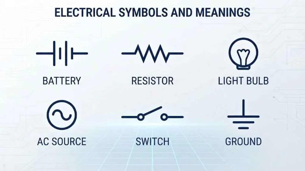
Electrical symbols and meanings become much easier to understand when they are grouped by function.
Power symbols
Power-related markings identify sources, supply types, polarity, or reference connections.
- + — positive DC terminal
- − — negative DC terminal
- ~ — commonly indicates AC
- ⎓ — commonly used to indicate direct current
- ⏚ — earth or ground symbol
The ground symbol deserves special attention. Ground can refer to a protective earth connection, a circuit reference point, or another defined grounding arrangement depending on the drawing.
Circuit component symbols
Common passive and active components include:
- R — resistor
- C — capacitor
- L — inductor
- D — diode
- LED — light-emitting diode
- Q — commonly used as a transistor reference designator
- T — commonly used for a transformer reference designator
Protection symbols
Protection devices are used to show how a circuit is protected from abnormal current or fault conditions.
- Fuse
- Circuit breaker
- Thermal overload device
- Surge protection device
Their exact graphical symbols should be read according to the applicable drafting standard.
Electrical symbols chart
An electrical symbols chart provides a quick visual reference. The following simplified chart focuses on commonly encountered components rather than trying to represent every possible symbol used in electrical engineering.
| Component | Common notation | Function |
| Resistor | R | Controls resistance/current relationship |
| Capacitor | C | Stores electrical energy |
| Inductor | L | Stores energy magnetically |
| Diode | D | Provides directional current behavior |
| LED | LED | Emits light |
| Switch | S | Controls circuit continuity |
| Fuse | F | Overcurrent protection |
| Circuit breaker | CB | Opens a circuit under defined fault conditions |
| Transformer | T | Transfers energy between electrical circuits |
| Motor | M | Produces mechanical movement |
| Generator | G | Produces electrical energy |
| Battery | B | Supplies electrical energy |
| Ground | ⏚ | Ground/reference connection |
| Lamp | L or designated lamp symbol | Indicates a light source |
| Relay | K or relay symbol | Electrically operated switching |
| Ammeter | A | Measures current |
| Voltmeter | V | Measures voltage |
Reference letters are not always universal. The graphical symbol and drawing legend are more important than relying on one letter alone.
20 electrical symbols
Here are 20 electrical components or symbols commonly encountered in electrical diagrams. Their exact graphical representation can depend on the applicable standard.
- Resistor — limits or controls resistance in a circuit.
- Capacitor — stores energy in an electric field.
- Inductor — stores energy in a magnetic field.
- Diode — provides primarily one-directional current behavior.
- LED — produces light when forward-biased under suitable conditions.
- Switch — opens or closes an electrical path.
- Fuse — provides overcurrent protection by opening when its rated operating condition is exceeded.
- Circuit breaker — interrupts a circuit under specified abnormal conditions.
- Transformer — transfers electrical energy between circuits through electromagnetic coupling.
- Battery — provides electrical energy from chemical reactions.
- Motor — converts electrical energy into mechanical energy.
- Generator — converts mechanical energy into electrical energy.
- Relay — uses an electrical control signal to operate contacts.
- Ground — identifies a grounding or reference connection.
- Lamp — represents a light-producing device.
- Ammeter — measures electrical current.
- Voltmeter — measures electrical voltage.
- Thermistor — resistance changes with temperature.
- Photodiode — responds electrically to light.
- Transistor — provides switching or amplification functions.
These are best learned by function. Once you understand what a component does, recognizing its schematic representation becomes much easier.
Electrical symbols for drawings
Electrical symbols for drawings are used in many types of technical documents, including wiring diagrams, schematic diagrams, installation drawings, control diagrams, and engineering documentation.
A drawing may contain several layers of information. Symbols identify the devices, while lines show electrical relationships or connections. Labels and reference numbers then provide additional information.
For example, a residential lighting drawing may show a supply, protective device, switch, lamp, and wiring connections. An industrial control drawing may contain relays, contactors, motors, sensors, overload devices, and control switches.
Always check:
- The drawing legend
- The project standard
- Reference designators
- Wire numbers
- Connection points
- Notes and abbreviations
- Manufacturer-specific symbols
This prevents mistakes caused by assuming that every drawing uses exactly the same conventions.
All electrical symbols
There is no practical single list containing every electrical symbol used worldwide. Electrical drawings cover many disciplines, standards, industries, and specialized systems.
Symbols can be organized into broad groups:
Passive component symbols
These include resistors, capacitors, inductors, thermistors, and related components.
Semiconductor symbols
These include diodes, LEDs, transistors, thyristors, and other semiconductor devices.
Electromechanical symbols
Motors, generators, relays, contactors, transformers, and switches fall into this category.
Protection symbols
Fuses, circuit breakers, overload devices, surge protection devices, and other protective equipment are represented in electrical documentation.
Measurement symbols
Ammeters, voltmeters, wattmeters, frequency meters, and other instruments may appear in control and measurement drawings.
Installation symbols
Building drawings may use symbols for outlets, switches, lighting points, distribution equipment, and other electrical installation components.
Because conventions vary, the legend accompanying a drawing is the best authority for interpreting a symbol in that particular document.
Electrical symbols for blueprints
Electrical symbols for blueprints help show where electrical equipment and installation points belong within a building or project.
A blueprint may include symbols for:
- Lighting fixtures
- Wall switches
- Receptacles or outlets
- Distribution panels
- Junction boxes
- Communication outlets
- Emergency lighting
- Smoke detection equipment
- Equipment connections
- Dedicated electrical loads
Unlike a detailed electronic schematic, a building blueprint is often concerned with where equipment is located and how the installation is arranged.
For example, a lighting fixture symbol placed inside a room indicates the planned location of the fixture, while a switch symbol near a doorway may identify the control point.
20 electrical symbols
A second group of 20 commonly encountered electrical symbols can be useful when building a study reference:
| No. | Symbol/component | Typical meaning |
| 1 | Ground | Electrical ground/reference |
| 2 | Switch | Manual circuit control |
| 3 | Push button | Momentary switching |
| 4 | Relay | Electrically controlled switching |
| 5 | Contactor | Power switching/control |
| 6 | Fuse | Overcurrent protection |
| 7 | Circuit breaker | Protective switching |
| 8 | Transformer | Voltage/energy transfer between circuits |
| 9 | Motor | Electrical-to-mechanical conversion |
| 10 | Generator | Mechanical-to-electrical conversion |
| 11 | Resistor | Resistance |
| 12 | Variable resistor | Adjustable resistance |
| 13 | Capacitor | Capacitance |
| 14 | Variable capacitor | Adjustable capacitance |
| 15 | Inductor | Inductance |
| 16 | Diode | Directional current behavior |
| 17 | LED | Light emission |
| 18 | Transistor | Switching or amplification |
| 19 | Ammeter | Current measurement |
| 20 | Voltmeter | Voltage measurement |
The visual shape of each symbol should be checked against the standard being used rather than copied from an unrelated diagram.
Hvac electrical symbols
HVAC electrical symbols are used in heating, ventilation, and air-conditioning drawings to identify equipment, controls, motors, sensors, and electrical connections.
Common HVAC-related items include:
- Thermostats
- Fans
- Blowers
- Compressors
- Motors
- Heating elements
- Cooling equipment
- Dampers
- Temperature sensors
- Pressure switches
- Contactors
- Relays
- Disconnects
- Control transformers
- Solenoid valves
An HVAC drawing may combine electrical symbols with mechanical and control-system symbols. This is why the drawing legend is particularly important.
For example, a thermostat may provide a control signal to equipment, while a contactor may control a larger electrical load. A motor symbol may represent a fan or blower motor rather than a generic motor.
Automotive electrical symbols
Automotive electrical symbols appear in vehicle wiring diagrams, service manuals, diagnostic documentation, and electrical system schematics.
Common automotive components include:
- Battery
- Alternator
- Starter motor
- Fuse
- Relay
- Ground connection
- Headlamp
- Tail lamp
- Turn signal
- Brake lamp
- Horn
- Motor
- Switch
- Sensor
- Connector
- Electronic control module
Automotive diagrams frequently use abbreviations and connector numbers alongside symbols. Wire colors, terminal numbers, and circuit identifiers can be just as important as the symbols themselves.
A battery symbol identifies the vehicle’s electrical supply, while a ground connection shows where a circuit returns to the vehicle’s electrical reference or chassis ground according to the system design.
Electrical symbols on blueprints
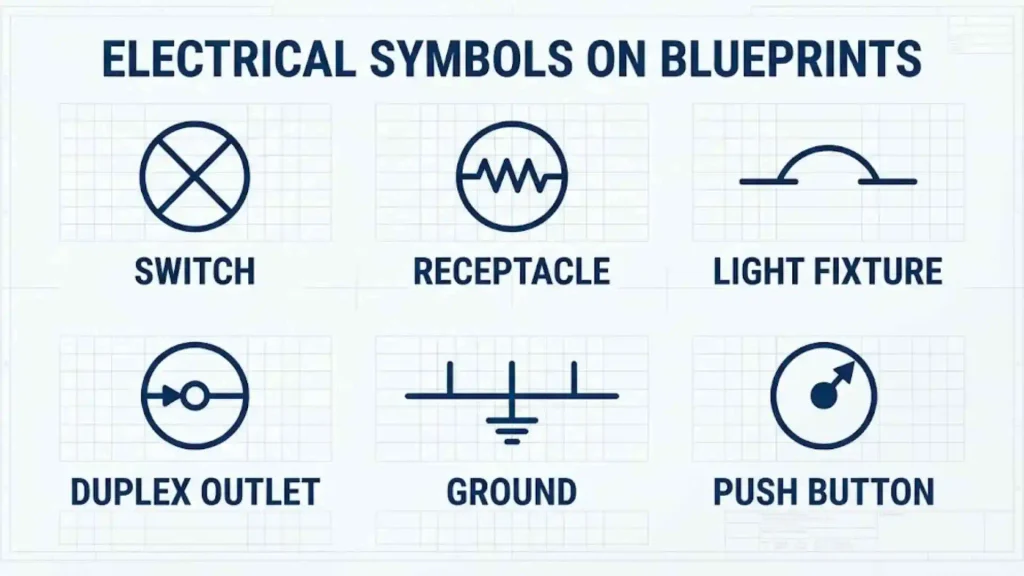
Electrical symbols on blueprints are normally read together with the architectural layout. Their location often matters as much as the symbol itself.
For example:
- A receptacle symbol indicates an outlet location.
- A lighting symbol identifies a light point.
- A switch symbol identifies a control location.
- A panel symbol identifies electrical distribution equipment.
- A junction box symbol can indicate an accessible connection point.
Blueprint symbols may be accompanied by labels such as circuit numbers, fixture types, mounting information, or equipment identifiers.
When reading a blueprint, first locate the legend. Then compare each symbol with the legend before interpreting its function.
Autocad electrical symbols
AutoCAD electrical symbols are used to create digital electrical drawings instead of drawing every component manually.
In an AutoCAD workflow, symbols can be inserted as blocks or through specialized electrical design tools. Reusable blocks make it easier to maintain consistent drawings.
A typical workflow is:
- Set up the drawing according to the project requirements.
- Establish layers for different electrical information.
- Insert or create the required symbols.
- Place symbols at their correct locations.
- Add wires or connection lines.
- Add labels and reference information.
- Check alignment and connectivity.
- Review the drawing against the project standard.
The exact commands and available libraries depend on the AutoCAD product and version being used.
Cad electrical symbols
CAD electrical symbols are digital versions of schematic or installation symbols used in computer-aided drafting.
CAD libraries can contain symbols for:
- Switches
- Outlets
- Lamps
- Motors
- Transformers
- Relays
- Sensors
- Protection devices
- Control equipment
- Panels
- Connectors
One advantage of CAD symbols is consistency. A carefully prepared symbol library allows the same component representation to be reused across multiple drawings.
When creating a CAD library, use consistent dimensions, layer settings, insertion points, attributes, and naming conventions. This makes future drawings easier to edit and maintain.
Drawing electrical symbols
Drawing electrical symbols by hand is still useful for learning circuit concepts and understanding diagrams. The goal is not to make every symbol look like a realistic object. The goal is to communicate electrical information clearly.
A good drawing should have:
- Clear symbols
- Readable labels
- Consistent linework
- Logical spacing
- Correct connections
- A useful legend
- Consistent orientation where applicable
When practicing, start with simple components such as resistors, switches, capacitors, batteries, lamps, and motors. Then move toward control circuits and more complex systems.
Avoid changing a symbol simply because a different shape looks easier to draw. In technical documentation, consistency matters.
Electrical symbols pdf
An electrical symbols PDF can work as a quick study sheet for students, electricians, designers, and technicians.
A useful PDF reference should ideally organize symbols into categories rather than placing hundreds of unrelated shapes on one page. A practical layout might include:
| Category | Examples |
| Basic components | Resistor, capacitor, inductor |
| Semiconductor | Diode, LED, transistor |
| Protection | Fuse, circuit breaker |
| Control | Switch, push button, relay |
| Machines | Motor, generator |
| Power | Battery, transformer, ground |
| Measurement | Ammeter, voltmeter |
| Building electrical | Outlet, lighting, panel |
Before relying on a downloaded reference for professional work, verify the symbols against the applicable standard or the project’s official legend.
How to use viseo to add electrical symbols
If you mean Visio, Microsoft Visio can be used to create technical diagrams with reusable shapes and connectors. The exact interface varies by Visio version and diagram type.
A general workflow is:
- Open Visio and create an appropriate electrical or engineering diagram.
- Open the relevant shapes or stencil collection.
- Search for the electrical component you need.
- Drag the symbol onto the drawing page.
- Connect components using connector tools.
- Add labels or reference designators.
- Align and space the symbols for readability.
- Review the finished diagram for missing or incorrect connections.
If a required symbol is not included in the available library, a custom shape may be possible depending on the Visio version and workflow. For professional documentation, make sure custom symbols are clearly defined in the drawing legend.
Electrical symbols autocad
Electrical symbols in AutoCAD can be managed efficiently when they are organized as reusable blocks or library items.
For a simple drawing, you can create a symbol as a block and insert it wherever needed. For larger electrical projects, specialized electrical design features can help with symbol libraries, wire numbering, component references, and project organization.
When preparing AutoCAD electrical symbols, pay attention to:
- Insertion point
- Scale
- Layer assignment
- Block attributes
- Orientation
- Text readability
- Reference numbering
- Connection points
A symbol that looks correct visually can still cause problems if its insertion point, attributes, or connection geometry are poorly prepared.
Bluebeam electrical symbols
Bluebeam can be useful when electrical drawings are being reviewed, marked up, or coordinated in PDF form.
Electrical teams may create reusable markup tools for frequently used symbols and annotations. These can help reviewers mark locations for outlets, lighting, equipment, changes, or other electrical items.
A practical Bluebeam workflow may include:
- Open the electrical PDF.
- Create or select an appropriate markup tool.
- Place the symbol or annotation on the drawing.
- Add comments when clarification is needed.
- Use consistent labels for repeated items.
- Save frequently used markups to a tool set where appropriate.
Bluebeam markups should not be confused with the original CAD symbols. A PDF markup is generally an annotation or review layer, while the original design symbol belongs to the source drawing.
Residential electrical symbols
Residential electrical symbols are commonly found on house plans, electrical layouts, renovation drawings, and construction documents.
Typical residential symbols represent:
- Ceiling lights
- Wall lights
- Single-pole switches
- Multi-location switches
- Receptacles
- GFCI receptacles
- Dedicated outlets
- Ceiling fans
- Smoke alarms
- Electrical panels
- Doorbell equipment
- Data or communication outlets
- Exterior lighting
The exact symbol depends on the drawing convention. For example, an outlet symbol on one plan may look different from the symbol used on another plan, while both may represent the same type of device.
Residential plans often use a legend that identifies fixture types and abbreviations. Always read the legend before interpreting an unfamiliar symbol.
Electrical symbols chart
A chart is most useful when it helps you compare components quickly. The following compact reference groups common electrical components by purpose.
| Group | Component | Main purpose |
| Control | Switch | Opens or closes a circuit |
| Control | Push button | Momentary control |
| Control | Relay | Electrical control of contacts |
| Protection | Fuse | Limits fault current by opening under specified conditions |
| Protection | Circuit breaker | Interrupts current under defined conditions |
| Passive | Resistor | Provides resistance |
| Passive | Capacitor | Provides capacitance |
| Passive | Inductor | Provides inductance |
| Semiconductor | Diode | Directional current behavior |
| Semiconductor | LED | Light emission |
| Semiconductor | Transistor | Switching or amplification |
| Power | Battery | DC electrical source |
| Power | Transformer | Transfers energy between circuits |
| Machine | Motor | Produces mechanical motion |
| Machine | Generator | Produces electrical output |
| Reference | Ground | Ground/reference connection |
| Measurement | Ammeter | Measures current |
| Measurement | Voltmeter | Measures voltage |
This type of chart is ideal for revision because it connects the component name with its main job.
Basic electrical symbols
Basic electrical symbols are the starting point for anyone learning to read electrical diagrams.
A beginner should first become familiar with:
- Resistor — controls resistance in a circuit.
- Capacitor — stores electrical energy.
- Inductor — stores energy in a magnetic field.
- Battery — supplies electrical energy.
- Switch — controls whether a circuit path is open or closed.
- Lamp — represents a light-producing load.
- Diode — controls current direction in a circuit.
- Fuse — provides overcurrent protection.
- Motor — converts electrical energy into mechanical motion.
- Ground — identifies a grounding or reference connection.
Start with simple diagrams. For example, a battery connected through a switch to a lamp demonstrates how a source, control device, load, and connecting conductors work together.
Once these basic ideas are clear, more complicated symbols become easier to understand.
Electrical symbols and meanings
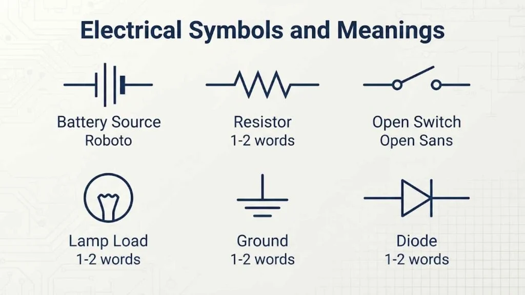
The meaning of an electrical symbol depends on its context, standard, and surrounding labels. This is especially important when reading unfamiliar technical drawings.
For example, a simple letter such as M may be used as a motor reference designation, but the actual motor symbol and the drawing’s labeling system provide the complete context.
Likewise, a ground symbol can have different roles depending on the system. It may represent protective earth, a circuit reference, or another defined grounding arrangement.
When interpreting a symbol, use this order:
- Identify the graphical symbol.
- Read its nearby label.
- Check the drawing legend.
- Look at connected components.
- Identify the applicable standard if available.
- Confirm the meaning before making a wiring or installation decision.
This approach is safer than relying on a generic symbol chart alone.
Common electrical symbols
Common electrical symbols appear repeatedly in circuit diagrams, building plans, industrial controls, automotive diagrams, and engineering documentation.
Some of the most useful symbols and components to recognize are:
| Component | What it represents |
| Resistor | Resistance |
| Capacitor | Capacitance |
| Inductor | Inductance |
| Diode | One-directional current behavior |
| LED | Light-emitting semiconductor |
| Switch | Manual or controlled circuit operation |
| Fuse | Overcurrent protection |
| Circuit breaker | Protective circuit interruption |
| Relay | Electrically operated switching |
| Transformer | Electromagnetic energy transfer |
| Motor | Mechanical output from electrical energy |
| Generator | Electrical output from mechanical energy |
| Battery | Electrical power source |
| Ground | Grounding/reference connection |
| Ammeter | Current measurement |
| Voltmeter | Voltage measurement |
How to read common symbols faster
Do not try to memorize every symbol at once. Learn symbols in functional groups. First learn sources and grounds, then control devices, passive components, protection devices, and finally specialized equipment.
Also remember that a symbol’s meaning is not always universal. Professional drawings normally provide a legend, standard reference, or other documentation that defines how symbols should be interpreted.
Frequently Asked Questions
What are electrical symbols used for?
Electrical symbols are used to represent components, devices, connections, and functions in electrical drawings. They make complex circuits and installations easier to understand without drawing each physical component realistically.
What is the most important electrical symbol to learn first?
For beginners, it is useful to start with basic components such as a battery, switch, resistor, lamp, ground, fuse, and motor. These provide a foundation for understanding simple circuits.
Are electrical symbols the same on every drawing?
No. Symbols can vary according to the applicable standard, industry, country, software, manufacturer, or project. The drawing legend should be used whenever the meaning of a symbol is uncertain.
Can electrical symbols be used in AutoCAD and Visio?
Yes. CAD and diagramming applications can provide libraries, blocks, shapes, or tools for creating electrical drawings. The exact features depend on the software and version.
Where can I find electrical symbols for blueprints?
Electrical symbols are commonly provided in blueprint legends, electrical drawing standards, CAD libraries, engineering references, and project documentation. For professional work, use the symbol definitions supplied with the specific project.
Conclusion
Electrical symbols make technical drawings much easier to read by giving components and electrical functions recognizable graphical representations. From basic resistors and switches to motors, protection devices, HVAC equipment, automotive components, and residential fixtures, each symbol communicates useful information.
The most reliable way to understand an unfamiliar electrical symbol is to consider its shape, label, connections, and drawing legend together. Generic charts are helpful for learning, but the project standard should take priority when interpreting a real electrical drawing.
For studying or drafting, keep a categorized electrical symbols chart nearby and learn symbols by function rather than memorizing shapes randomly. This makes electrical diagrams, blueprints, CAD drawings, and wiring documentation much easier to understand.

Hi, I’m Sienna Brooks, and I believe that the right words can inspire, comfort, and empower people at every stage of life. For as long as I can remember, I’ve been drawn to meaningful quotes and the stories behind them. I love curating collections of inspirational, motivational, and heartfelt quotes that resonate with readers around the world.
Through my writing, I strive to help others find encouragement, whether they’re celebrating life’s happiest moments or navigating its biggest challenges. I believe that wisdom is timeless, and I’m passionate about sharing words that leave a lasting impact.
I am the author of Reflections in Words and The Journey of Inspiration, two books dedicated to exploring the beauty and power of timeless quotes.
 Rowan Sinclair Rowan Sinclair