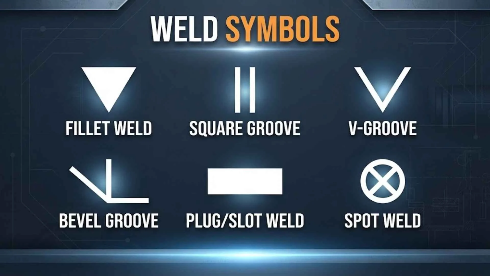
Weld symbols are a visual language used on engineering and fabrication drawings to tell a welder what type of weld is required, where it should be placed, and how it should be prepared. Learning these symbols makes technical drawings much easier to understand.
Common examples include fillet, groove, plug, slot, spot, seam, and surfacing weld symbols. The symbol itself is only part of the information. The reference line, arrow, dimensions, contour, finish marks, and supplementary details can all change how the welding instruction should be interpreted.
This guide explains weld symbols from the basics through AWS, ANSI, and ISO conventions. It includes common symbols, practical examples, drawing-reading tips, charts, and guidance for finding or creating useful PDF references.
Basic Weld Symbols
Basic weld symbols are graphical marks that identify the type of weld required on a drawing. They are normally placed in relation to a reference line and arrow.
Some common weld types include:
| Weld type | Basic symbol idea | Typical use |
| Fillet | Triangle | Joining members at an angle |
| Groove | Groove-specific outline | Preparing edges for a groove weld |
| Plug | Rectangular symbol | Joining through a hole |
| Slot | Elongated slot symbol | Joining through an elongated opening |
| Spot | Circle | Resistance spot welding |
| Seam | Circle with seam indication | Resistance seam welding |
| Stud | Stud symbol | Attaching studs |
| Surfacing | Curved surface indication | Depositing weld metal on a surface |
The exact graphical form should always be read according to the applicable welding standard and drawing system.
Weld Symbols And Meanings
A weld symbol communicates more than the name of a weld. Its position and accompanying information can specify important requirements.
A typical welding callout may contain:
- Arrow — points toward the joint.
- Reference line — carries the welding symbol.
- Basic weld symbol — identifies the weld type.
- Dimensions — specify size, length, pitch, depth, or other measurements.
- Tail — may contain process, specification, or other instructions.
- Contour symbol — describes the desired weld face shape.
- Finish symbol — indicates the required finishing method when applicable.
For example, a fillet weld symbol tells you the weld type, while a number placed near it can provide the specified weld size.
Weld Symbols On Drawings
Weld symbols on drawings allow designers and fabricators to communicate welding requirements without drawing every weld in detail.
When looking at a drawing, first identify the reference line and arrow. Then examine the weld symbol and any dimensions or supplementary marks.
A useful reading sequence is:
- Find the arrow pointing toward the joint.
- Locate the reference line.
- Identify the basic weld symbol.
- Determine which side of the joint is specified.
- Read the dimensions.
- Check length and pitch information.
- Look for contour or finish requirements.
- Read any information in the tail.
- Check the drawing notes and applicable welding standard.
Never rely on the symbol alone when the drawing contains additional notes.
How To Read Weld Symbols
Learning how to read weld symbols becomes easier when you treat the drawing as a collection of separate pieces of information.
Start with the arrow. It identifies the joint being referenced. Next, look at the reference line, where the basic weld symbol is placed.
Then examine the position of the symbol relative to the reference line. Under commonly used AWS conventions, this position helps identify the arrow side or other side of the joint. However, the exact interpretation should be confirmed against the standard used by the drawing.
After identifying the weld type, check the numbers. Dimensions can specify weld size, length, spacing, depth, or other requirements.
Finally, inspect supplementary symbols and notes. A drawing can specify a particular contour, finish, intermittent weld pattern, welding process, or other requirement.
Understanding Weld Symbols
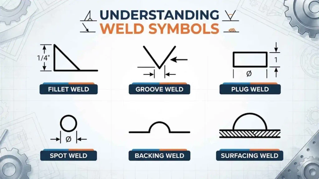
Understanding weld symbols means reading the complete welding callout rather than memorizing isolated shapes.
Consider a simple example: a triangular fillet symbol identifies a fillet weld. If a dimension is added, it can specify the required weld size. If length and pitch information are included, they can indicate an intermittent weld pattern.
This is why two drawings containing the same basic weld symbol can still require different welding work.
The most important habit is to read the symbol, location, dimensions, and notes together.
Types Of Weld Symbols
Weld symbols can be grouped according to the type of joint or welding operation they represent.
Common categories include:
Fillet Weld Symbols
Used for many T-joints, lap joints, and corner joints.
Groove Weld Symbols
Used when the edges of the members are prepared to create a groove for the weld.
Plug And Slot Weld Symbols
Used when weld metal is deposited through holes or slots in one member.
Spot And Seam Weld Symbols
Associated with resistance welding applications.
Stud Weld Symbols
Used to specify attachment of studs.
Surfacing Weld Symbols
Used when weld metal is deposited onto a surface rather than primarily joining two separate members.
The actual symbol and its application should be checked against the standard governing the drawing.
Common Weld Symbols
Some weld symbols appear frequently in fabrication drawings.
| Symbol type | What it identifies |
| Fillet | Fillet weld |
| Groove | Groove weld |
| Plug | Plug weld |
| Slot | Slot weld |
| Spot | Spot weld |
| Seam | Seam weld |
| Stud | Stud weld |
| Surfacing | Surfacing weld |
The symbol is normally combined with other drawing information. A basic symbol without dimensions may not provide enough information to fabricate the joint correctly.
All Weld Symbols
A complete collection of welding symbols can become extensive because different weld types have their own basic symbols, variations, dimensions, supplementary marks, and conventions.
For practical study, it helps to divide them into groups:
- Fillet welds
- Groove welds
- Plug welds
- Slot welds
- Spot welds
- Seam welds
- Stud welds
- Surfacing welds
- Back or backing-related indications
- Contour and finish indications
- Intermittent weld indications
- Field weld indications
- Weld-all-around indications
There is no single universal symbol system covering every drawing convention worldwide. AWS-based drawings and ISO-based drawings can use different conventions, so identifying the governing standard is essential.
Weld Symbols Chart
A basic study chart can be organized like this:
| Category | Symbol family | Main purpose |
| Fillet | Fillet symbol | Joining members at an angle |
| Groove | Groove symbols | Edge-prepared joints |
| Plug | Plug symbol | Welding through a hole |
| Slot | Slot symbol | Welding through a slot |
| Spot | Spot symbol | Resistance spot welding |
| Seam | Seam symbol | Resistance seam welding |
| Stud | Stud symbol | Attaching studs |
| Surfacing | Surfacing symbol | Depositing weld metal on a surface |
For shop use, a chart should also show dimensions, arrow/reference-line conventions, supplementary symbols, and the standard being followed.
Weld Symbols Explained
Weld symbols work like a compact set of instructions. The basic symbol answers what type of weld, while other information answers where, how much, how long, and what finish is required.
For example, a drawing may specify a fillet weld and then provide its size and length. Another drawing may use the same weld type but require intermittent welds at a specified spacing.
This makes welding symbols efficient. A relatively small graphic can communicate information that would otherwise require several sentences.
Weld Symbols With Examples
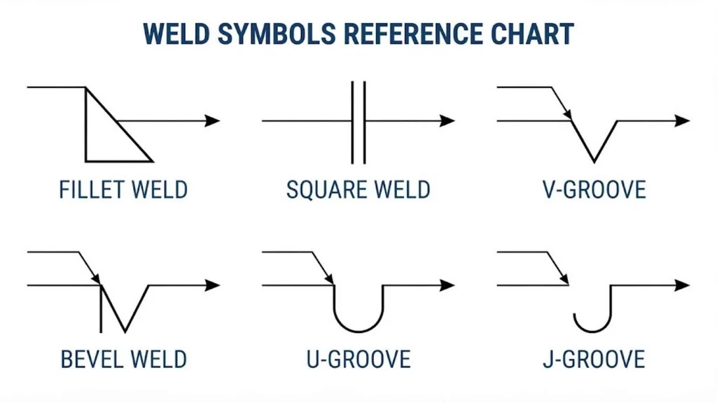
Here are simplified examples of how welding callouts communicate information:
Example 1: Fillet weld
A triangular fillet symbol identifies the weld type. A dimension beside the symbol can specify the required fillet size.
Example 2: Intermittent fillet weld
A fillet symbol accompanied by length and pitch information can specify separate weld segments rather than one continuous weld.
Example 3: Groove weld
A groove symbol identifies the type of prepared joint. Additional dimensions can describe the required preparation and weld size.
Example 4: Field weld
A supplementary field-weld indication can tell the fabricator that the weld is intended to be made at the installation site rather than in the shop.
These are simplified explanations. The actual drawing should always be interpreted according to its governing standard.
Weld Symbols And Meaning
The meaning of a welding symbol depends on several elements working together.
A useful way to remember this is:
Symbol = weld type
Position = location or side information
Numbers = dimensions
Additional marks = supplementary requirements
For example, the same fillet weld symbol can represent different fabrication requirements when its dimensions, length, pitch, or location change.
Reading the entire callout prevents mistakes caused by focusing on the basic symbol alone.
Weld Symbols Meaning
The meaning of an individual weld symbol is usually tied to a particular weld type.
A fillet symbol indicates a fillet weld.
A groove symbol identifies a groove weld configuration.
A plug symbol indicates a plug weld.
A slot symbol identifies a slot weld.
A spot symbol is associated with a spot weld.
A seam symbol identifies a seam weld.
A stud symbol is used for stud welding.
A surfacing symbol indicates surfacing weld work.
The surrounding information determines the complete welding requirement.
Fillet Weld Symbols
The fillet weld symbol is commonly represented by a right-triangle shape placed on the reference line.
Fillet welds are widely used for joints such as:
- T-joints
- Lap joints
- Corner joints
A fillet weld callout may specify the weld size, length, and spacing. For an intermittent fillet weld, the drawing can provide both the length of each weld segment and the pitch between successive segments.
A simple conceptual example is:
Fillet symbol + 6 mm dimension → 6 mm specified fillet size
The exact placement and interpretation of dimensions should follow the drawing standard.
Fillet Weld Symbols
Fillet weld symbols are among the first symbols most welding students learn because fillet welds are common in fabricated structures.
The triangular symbol should not be confused with a triangular decorative graphic. Its position in the welding callout gives it its technical meaning.
When reading one, check:
- Which joint the arrow identifies.
- Which side is specified.
- The weld size.
- Whether the weld is continuous or intermittent.
- Any length or pitch information.
- Any contour or finishing requirement.
A drawing can therefore turn a simple triangular mark into a detailed fabrication instruction.
Groove Weld Symbols
Groove weld symbols represent welds made in a groove between members. Different groove preparations have different symbols.
Common groove-weld categories include:
- Square groove
- V-groove
- Bevel groove
- U-groove
- J-groove
- Flare-V groove
- Flare-bevel groove
The symbol can be accompanied by dimensions describing details such as groove size, depth, root opening, or other required characteristics.
Groove symbols are particularly important because the joint preparation can significantly affect how the parts must be fabricated and welded.
Pipe Weld Symbols
Pipe welding drawings may use the same fundamental welding-symbol system while also providing additional information about the pipe joint.
A pipe-welding drawing can identify:
- Weld type
- Joint location
- Weld size
- Groove preparation
- Root details
- Circumferential weld requirements
- Inspection requirements
- Welding procedure information
A pipe drawing may contain information beyond the weld symbol itself, so welders should read the drawing notes, dimensions, specifications, and applicable codes together.
Pipe weld symbols should not be confused with symbols for pipe fittings, valves, or process-flow diagrams. Those are separate drawing conventions.
Weld Symbols AWS
AWS welding-symbol conventions are widely used in American welding documentation. The American Welding Society publishes standards covering welding symbols, including AWS A2.4, Standard Symbols for Welding, Brazing, and Nondestructive Examination.
AWS-based drawings commonly use a reference line, arrow, basic weld symbols, dimensions, supplementary symbols, and other information to communicate requirements.
When working from an AWS-based drawing, use the applicable edition of the standard specified by the project rather than relying on a generic internet chart.
AWS Weld Symbols
AWS weld symbols provide a standardized graphical method for communicating welding requirements.
A typical AWS-style callout can contain:
- Reference line
- Arrow
- Basic weld symbol
- Dimensions
- Tail
- Supplementary symbols
- Specifications or process information
The tail can be omitted when it is unnecessary. When present, it may contain information such as a welding process, specification, or other instruction.
For professional fabrication, the project specification and applicable AWS standard should take priority over simplified online examples.
ANSI Weld Symbols
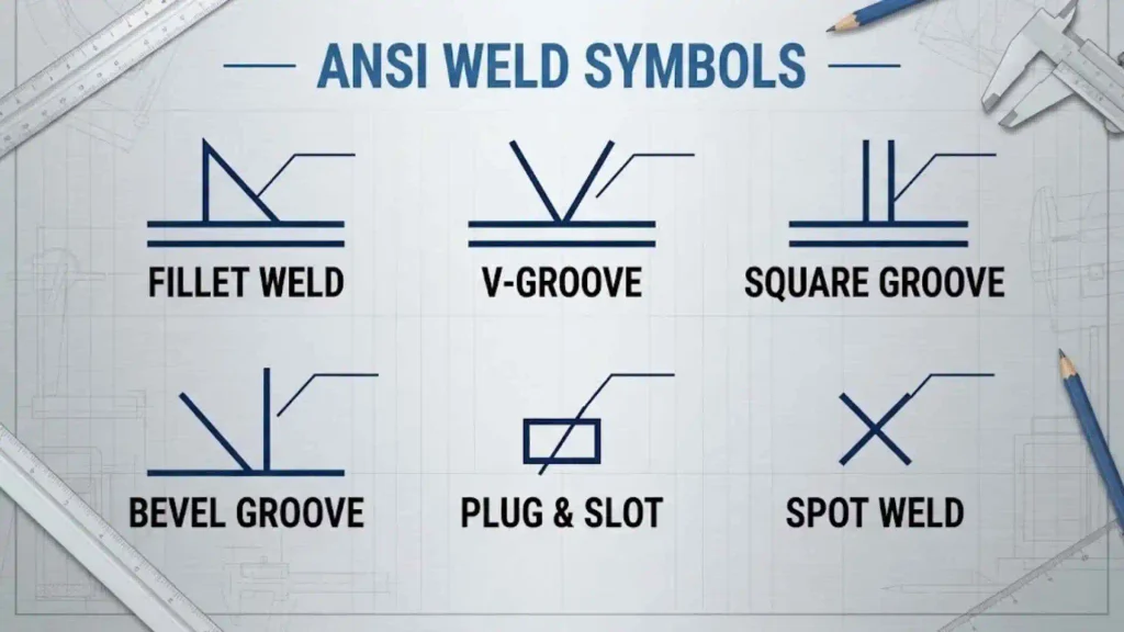
ANSI has historically been involved in American standardization, but welding-symbol requirements should not be treated as a generic “ANSI symbol set” without checking the specific standard referenced by the drawing.
In many U.S. welding contexts, AWS standards provide the detailed welding-symbol conventions used by engineers, designers, inspectors, and fabricators.
If a drawing mentions ANSI, AWS, or another specific standard, identify the exact document and edition. Standards can be revised, and the applicable edition matters.
ISO Weld Symbols
ISO welding symbols are used in international technical documentation and follow conventions established through the ISO system.
ISO and AWS approaches share the same broad purpose—communicating welding requirements graphically—but their conventions are not identical in every detail.
One important difference can involve how the symbol’s relationship to the reference line communicates the relevant side of the joint. This is why an AWS-based chart should not automatically be used to interpret an ISO drawing.
When working internationally, always identify whether the drawing follows an ISO welding-symbol standard or another regional convention.
Weld Symbols And Meanings
The easiest way to learn weld symbols is to separate the information into layers.
First layer: identify the weld.
Is it a fillet, groove, plug, slot, spot, seam, stud, or surfacing weld?
Second layer: identify the location.
Use the arrow and reference-line convention applicable to the drawing standard.
Third layer: identify the dimensions.
Numbers can communicate weld size, length, spacing, or other dimensions.
Fourth layer: check supplementary information.
Look for contour, finish, field-weld, all-around, tail, and drawing-note information.
This approach is more reliable than trying to memorize every possible complete callout.
Frequently Asked Questions
What Are Weld Symbols Used For?
Weld symbols are used on technical drawings to communicate the type, location, size, extent, and other requirements of a weld without having to draw the finished weld in detail.
What Is The Most Common Weld Symbol?
The fillet weld symbol is one of the most commonly encountered welding symbols. It is used for many T-joints, lap joints, and corner joints.
What Is The Difference Between AWS And ISO Weld Symbols?
AWS and ISO are different standards systems, and their welding-symbol conventions are not identical in every detail. The applicable standard should always be identified before interpreting a drawing.
How Do You Read A Weld Symbol?
Start with the arrow and reference line, identify the basic weld symbol, determine the applicable side convention, then read dimensions, supplementary symbols, and drawing notes.
Can I Use A Weld Symbols PDF As A Professional Reference?
A PDF can be useful for study and quick reference, but professional work should rely on the applicable project drawing, specification, and current edition of the relevant welding standard.
Conclusion
Weld symbols provide a compact way to communicate detailed fabrication instructions. Once you understand the reference line, arrow, basic symbols, dimensions, and supplementary marks, technical welding drawings become much easier to read.
Fillet and groove symbols are especially important, while plug, slot, spot, seam, stud, and surfacing symbols broaden the system. AWS and ISO conventions also need to be kept separate because their drawing practices are not identical in every respect.
For studying, a clear weld-symbol chart or PDF can be valuable, but always verify technical information against the standard specified by the drawing. That simple habit helps prevent errors when a symbol carries an important manufacturing requirement.

Hi, I’m Asher Monroe, a writer who believes that meaningful words have the power to inspire change and bring people closer to their dreams. I have always been fascinated by the beauty of quotes and the way a simple message can provide motivation, hope, and comfort.
I enjoy creating content around inspirational quotes, life lessons, success stories, and positive thoughts that help readers find encouragement in their everyday lives. My goal is to share words that connect with people and remind them of their inner strength.
Through my writing, I explore the ideas of personal growth, confidence, and the importance of staying inspired through every chapter of life.
I am the author of Words That Move the Soul and The Path of Endless Inspiration, two books focused on the power of wisdom, positivity, and meaningful thoughts.
 Sienna Brooks
 Rowan Sinclair Rowan Sinclair